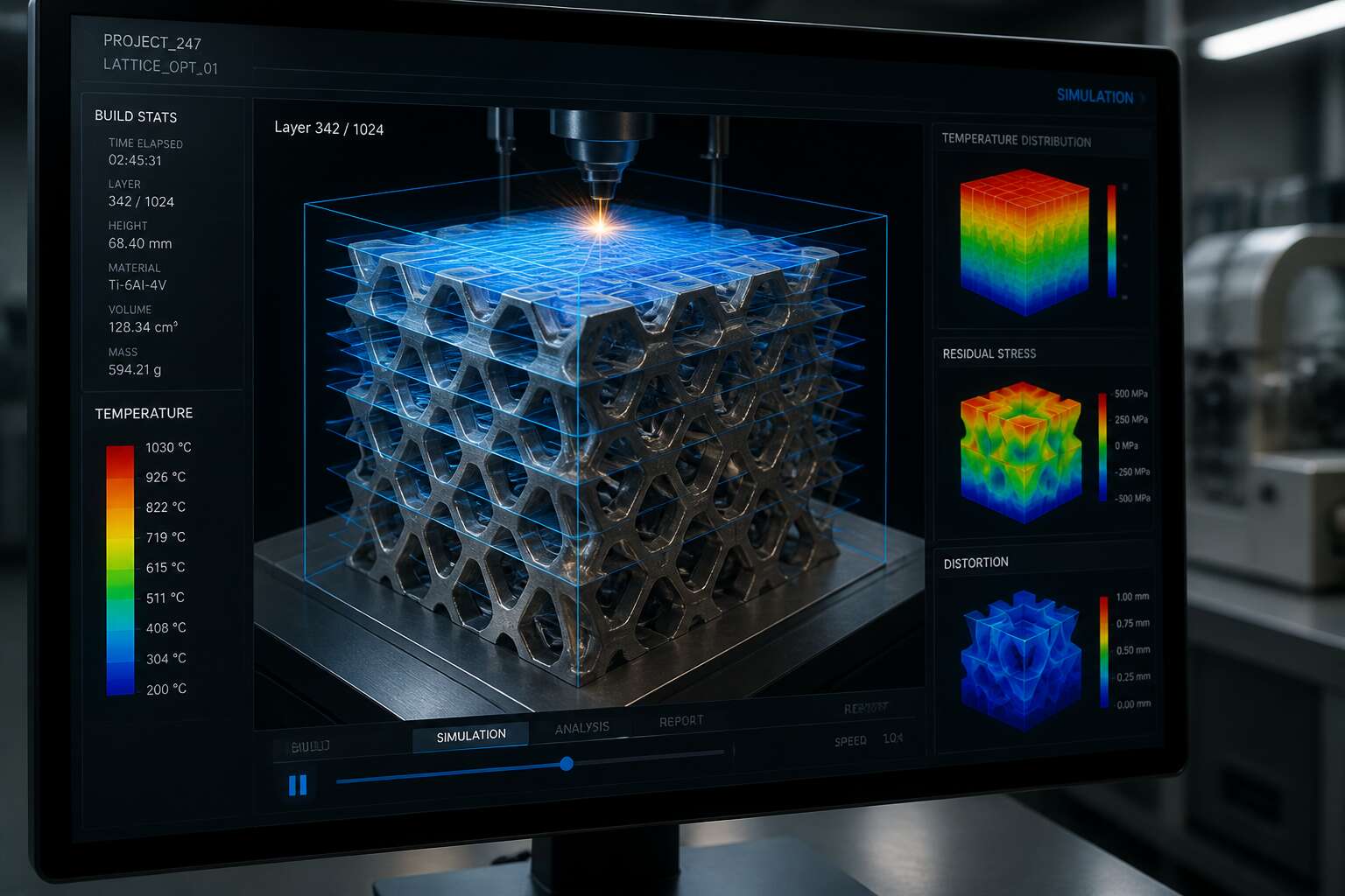
The Strategic Value of Simulation in Additive Manufacturing
Cutting Costs by Reducing Physical Trial-and-Error
Each failed build can consume thousands of rand in metal powder and machine time. That is why additive manufacturing simulation has shifted from a luxury to a financial necessity for South African engineering firms. Instead of validating every design on the factory floor, teams can probe virtual builds for thermal distortion, residual stress, and support failure before the laser ever fires. This approach cuts costs by reducing physical trial-and-error, turning expensive guesswork into a precise digital rehearsal.
The strategic value becomes clear when you consider the variables that cause defects: wall thickness, overhang angles, and cooling rates all interact unpredictably. Simulation lets you test these variables in a controlled environment, so you send only the most robust build files to the printer. Consider the direct savings:
- Eliminated reprints from failed supports
- Reduced material waste on non-viable geometries
- Fewer machine hours spent on experimental runs
For a small batch manufacturer in Johannesburg, one successful simulated build can offset the software investment entirely. The result is a workflow where learning happens in the cloud, not on the build plate, and every printed part carries a higher probability of success.
Minimizing Defects Before the First Print
Every layer of metal powder hides a potential failure. A subtle thermal gradient can warp a component beyond tolerance, and the defect only appears after several hours of printing. Additive manufacturing simulation changes that timeline by exposing these failures in the digital phase. The strategic value lies in interrogation, more than prediction. You can examine each simulation layer to inspect residual stress patterns, or test how a support structure behaves under extreme cooling.
Consider the typical defect categories that simulation targets:
- Thermal distortion from uneven heat dissipation
- Delamination between build layers
- Support collapse under residual stress
Each of these defects produces a traceable indicator in the simulation data. Once you learn to read those indicators, you can skip the expensive step of destructive testing. The printer then confirms what simulation already told you. Additive manufacturing simulation narrows the field to designs that survive thermal and stress analysis.
Accelerating Qualification and Certification Processes
Qualification processes in metal printing often exceed six months. Regulators demand evidence, and physical testing generates costly, time-consuming data. Additive manufacturing simulation compresses that timeline by producing repeatable, inspectable virtual evidence. Each simulation run documents thermal behavior and stress responses across every layer. That digital record supports certification arguments without sacrificing a single powder batch. For South African manufacturers entering aerospace or medical markets, this accelerates approval pathways.
Consider what simulation reveals during qualification:
- Consistent residual stress profiles across repeated builds
- Correlation between simulated and measured distortion
- Process window boundaries for alloy-specific parameters
These data points become the foundation of a certification dossier. The result is a faster route from prototype to production, with confidence built on analysis rather than guesswork.
Core Physical Phenomena Modeled in Simulation-Driven AM
Residual Stress and Distortion Prediction in Metal Parts
Metal powder meets a moving heat source, and the dance begins. But this dance follows strict physical rules. Additive manufacturing simulation models these rules to predict residual stress and distortion in metal parts. Core phenomena include:
- Rapid thermal cycling that creates uneven expansion and contraction
- Solid-state phase transformations that alter material volume
- Creep and plasticity at elevated temperatures
These mechanisms interact in ways that are difficult to observe directly. Simulation reveals how heat builds up across layers and how that heat freezes into internal stress. For example, a thin wall may warp not because of poor design, but because of the sequence of thermal events. The value lies in seeing the stress field before the part leaves the build chamber. That is a powerful form of foresight for any metal workshop.
Melt Pool Dynamics and Microstructure Formation
Beneath the laser’s gaze, a molten pool breathes, its life measured in milliseconds. In additive manufacturing simulation, this pool is not a shapeless puddle but a precise theater of thermal violence. The size, shape, and temperature gradient of this liquid eye dictate everything that follows.
- Marangoni convection driving fluid flow
- Evaporation and recoil pressure effects
- Thermal capillary forces at the pool boundary
These interactions forge the pool’s signature. As the pool cools, solidification begins. Columnar grains chase the heat, equiaxed grains resist. Additive manufacturing simulation captures this race, predicting the resulting microstructure, its phases, and its anisotropy. It reveals how a cooling rate of ten thousand degrees per second transforms a simple alloy into a lattice of hidden strengths and lurking weaknesses.
Fluid Flow and Powder Spreading Simulations
Before the first layer ever fuses, the powder bed holds its own quiet complexity. In additive manufacturing simulation, we watch particles cascade and settle, each grain responding to gravity, friction, and van der Waals forces. This is not background noise; it dictates density and surface finish. Meanwhile, the melt pool’s behavior emerges from a violent interplay of surface tension and viscous flow. Our models track this liquid motion, revealing how:
– Marangoni convection sweeps material outward
– Capillary forces pull molten metal inward
– Recoil pressure from vaporization shapes the pool’s depth
These fluid dynamics determine whether a part becomes a network of strength or a scaffold of voids. Powder spreading simulations likewise expose how roller speed and layer thickness alter packing. When we get these physical realities right, the machine becomes predictable. That is the quiet power of simulation-driven design!
Choosing the Right Simulation Approach for Your AM Application
Process-Level Simulation vs. Part-Level Structural Analysis
Choosing between process-level simulation and part-level structural analysis hinges on the question you need answered. Process-level models track the physical build, capturing thermal history and layer-by-layer deposition. Part-level analysis evaluates a final component under service loads. Within additive manufacturing simulation, these are distinct epistemic domains.
For South African manufacturers, the decision often depends on component criticality. I have watched teams waste months chasing the wrong level of fidelity. A bracket for mining equipment may only require static validation. An aerospace impeller demands process fidelity. The granularity of your additive manufacturing simulation must mirror the risk you are willing to carry.
Consider the practical signals:
- Process-level simulation suits new alloys or novel geometries where failure modes are unknown.
- Part-level analysis fits certified legacy designs relocated to an additive workflow.
- Hybrid workflows surface when build-induced stress affects in-service performance.
The mismatch between these approaches causes more failed prints than material variation. Match the model to the decision, not the software.
Evaluating Commercial Software Platforms and Open-Source Alternatives
Choosing the right simulation tool starts with honesty about your team’s arithmetic. Commercial platforms in additive manufacturing simulation offer validated material libraries, polished interfaces, and responsive support. Open-source alternatives give you complete visibility into the code, but the price is your own time and expertise.
South African manufacturers weigh these options against their own constraints. A local supplier validating certified legacy parts may need the reliability of a commercial solver. A university laboratory investigating new alloys might find open-source frameworks more accommodating.
Here is what separates a useful platform from an impressive one:
- The ease of calibrating your specific machine parameters
- The clarity of the output for non-specialists
- The cost of training multiple engineers
- The ability to automate repetitive workflows
A platform that cannot reproduce your local conditions is a liability.
Balancing Simulation Fidelity against Computational Cost
A single high fidelity melt pool simulation can occupy a workstation for days, producing a detailed map of one tiny layer of metal. A coarse part level model returns answers in minutes, but with less certainty about local physics. In many South African workshops, we weigh that fidelity against the cost of delay.
The practical approach is layered. Start with part level analysis to identify risk zones, then run local melt pool studies only for those regions. This keeps additive manufacturing simulation affordable without sacrificing the insights that matter. Before committing to a solver, ask:
- What decision will this simulation inform?
- How many iterations will the trial require?
- Which failure modes carry the highest cost?
If the answers point to a single high stakes geometry, higher fidelity justifies the computational price. If they point to routine builds, a lighter model preserves your throughput.
Matching Simulation Tools to Specific Additive Manufacturing Technologies
Powder bed fusion and directed energy deposition share the word additive, but they share almost nothing else. The thermal histories, residual stress fields, and failure modes are distinct. An additive manufacturing simulation calibrated for one technology will mislead you if applied to another.
Laser powder bed fusion demands attention to melt pool stability and powder behavior. Wire arc additive manufacturing shifts the focus to interpass temperature and distortion accumulation. The matching of solver to process determines the value of any additive manufacturing simulation output. In many South African workshops, packages are chosen for brand recognition rather than fit to the machine on the floor. That mismatch produces confident answers to the wrong questions.
- Powder bed fusion: thermal gradients and melt pool stability
- Directed energy deposition: deposition sequencing and stress buildup
- Binder jetting: sintering shrinkage and green part handling
Practical Steps to Integrate Simulation into an AM Production Workflow
Building a Validated Digital Material Database
In our work with South African manufacturers, the gap between simulation and production almost always traces back to material data. A validated digital material database makes additive manufacturing simulation a practical tool for the shop floor.
The first step is to standardise test coupons. Build them under the same process conditions used for production parts. Then capture thermal and mechanical properties from each batch. Many operators treat the database as a one-time project. Instead, treat it as a living record.
- Use consistent scan strategies and build orientations.
- Record every parameter, including layer thickness and chamber temperature.
- Update the database after each machine calibration.
When this data flows back into your models, the predictions align with what actually happens on the build plate. That alignment is what makes additive manufacturing simulation reliable for daily decisions!
Optimizing Build Orientation and Support Structures Virtually
The foundation you have built with validated material data changes how you approach each new build. Additive manufacturing simulation becomes a tool for interrogation, not confirmation. The first question is always about orientation. Every degree of rotation shifts the thermal history, the stress vectors, and the surface quality. You can explore these variations without consuming powder or machine time.
Simulation lets you test the most aggressive orientations first, the ones that reduce build height and shorten cycle time. You see the distortion risk before it materialises in metal. The same logic applies to supports. Instead of adding supports for every overhang, you can model the actual need.
A typical analysis sequence might look like this:
1. Import the geometry and assign the validated material properties.
2. Run a residual stress simulation for the proposed orientation.
3. Analyse the deformation results to identify high-risk zones.
4. Add supports only where the simulation shows movement exceeding your tolerance.
This iterative process sharpens your intuition. You start to predict how a thin wall will behave before the simulation confirms it. When a part passes the virtual test, you send it to the floor with confidence. When it fails, you have the data to explain why. The integration is not about replacing skill. It is about giving your engineers a sharper lens on the physics inside the chamber.
Connecting Generative Design with Simulation Feedback Loops
There is a quiet urgency in the move from a successful prototype to a production line. The economics demand that the first batch of parts emerges from the powder bed as finished goods, not as experiments. This is where the true value of additive manufacturing simulation becomes tangible, not as a theoretical exercise but as a daily operational tool.
To integrate simulation into a production workflow, you must first establish a single source of truth for your process parameters. Your simulation model is only as useful as the data it digests. Build a protocol where the build file, the material lot, and the machine settings are captured before the print begins. This data feeds directly into the predictive model, creating a live feedback loop that prevents the same errors from repeating.
Connecting generative design with simulation feedback loops closes the circle between what you want to build and what your machine can actually produce. Generative design offers a universe of organic, material-efficient geometries. However, these shapes often ignore the thermal constraints of the build chamber. Simulation steps in to review the generated geometry, calculating the residual stress that will accumulate during the layer-by-layer process. The software identifies areas where the design will warp or crack, sending this data back to the generative algorithm to refine the shape.
The workflow requires discipline. Here is the sequence we use to vet every part that enters production:
1. Export the generative design geometry and assign the physical material properties.
2. Run a fast, low-fidelity thermal simulation to spot immediate problem zones.
3. Refine the mesh in those specific areas for a high-fidelity distortion analysis.
4. Compare the simulated deformation against the critical tolerance dimensions.
5. Iterate the generative constraints to remove stress concentrations.
The goal is to let the generative engine explore its creative space, while a virtual sentinel checks its work. This integration shifts the burden of trial-and-error from the physical machine to a digital environment. It turns a costly flaw in a titanium bracket into a simple script revision. This is how a factory floor in Johannesburg or Durban can compete on an international stage, trading safety margins for confidence and raw material for pure speed.
Simulating Full Build Platforms to Prevent Batch Failures
A single warped part can halt an entire production shift, and when that part sits among dozens of others on a packed platform, the failure multiplies across the batch. We now run additive manufacturing simulation on the full build platform before committing powder to the chamber. This scale of analysis reveals how heat from one component affects its neighbor, exposing deformation patterns that part-level checks would miss.
To integrate this into our daily workflow, we follow a fixed sequence:
- Map the full platform layout from the actual machine build file.
- Run a coarse thermal sweep to locate hot spots and cool zones.
- Refine the mesh around critical areas using verified build data.
- Adjust part spacing or orientation from the simulated distortion field.
This method turns batch planning into a deliberate act! When additive manufacturing simulation guides the platform layout, the machine runs with confidence, and the scrap rate drops to near zero.
Integrating Simulation Results into Process Planning and CAM
A simulation result that never reaches the machine is just a report. We integrate additive manufacturing simulation into process planning by treating the output as editable data. The distortion field from the platform analysis feeds directly into the CAM system. Toolpaths adjust. Support points shift. The build file changes before powder hits the chamber.
We follow a simple loop:
- Export the deformation map from the solver.
- Overlay it onto the CAM coordinate system.
- Adjust slice parameters where deviation exceeds tolerance.
- Re-run the simulation on the modified file.
Each cycle tightens the correlation between predicted and actual output. Additive manufacturing simulation becomes the link between design intent and physical reality. The machine runs with fewer surprises, and rework drops. That is the practical payoff.
Using Simulation Data for Real-Time Monitoring and Closed-Loop Control
The data stream is the true operator. Additive manufacturing simulation no longer ends at the build file. It lives inside the chamber, reading the melt pool, the recoater blade, the thermal history. To integrate it into production, start by wiring simulation outputs to in-situ sensors. Then let the model compare predicted strain against measured values. When deviation appears, the system adjusts laser power or scan speed. This is closed-loop control. One practical sequence: first, map sensor positions; second, calibrate the simulation baseline; third, set deviation thresholds. Additive manufacturing simulation becomes a sentinel, not a report.
Common Challenges and How Leading Manufacturers Overcome Them
Managing the Complexity of Multi-Physics Interactions
Multi-physics interactions present a stubborn challenge in additive manufacturing simulation. Thermal gradients, fluid flow, and structural stress rarely cooperate cleanly. Leading manufacturers overcome this by using coupled solvers that exchange data at every timestep. They build digital threads that link process parameters to final properties. A common approach starts with a simplified thermal model, then layers fluid dynamics once the heat source is calibrated. Some teams adopt a staggered strategy. Others use monolithic coupling for extreme accuracy. The result is fewer failed builds and less wasted material. To manage this complexity, manufacturers rely on:
- Calibrated material properties for each powder batch
- High-performance computing clusters for iterative runs
- Cross-disciplinary review boards for model assumptions
These steps turn chaotic physics into a manageable workflow.
Overcoming Material Data Scarcity and Variability
Powder batches refuse to be identical. Particle size, moisture content, and thermal conductivity drift between deliveries, and even within a single silo. Material data scarcity makes this unpredictability dangerous, particularly for suppliers serving demanding industries. Without reliable input, additive manufacturing simulation rests on hollow hope.
Leading manufacturers respond with ritual discipline. They characterise every incoming batch. They build statistical profiles instead of single-point values. Their protocols include:
- Measuring particle distribution for each batch
- Tracking humidity exposure during storage
- Validating thermal properties against physical coupons
This data feeds their additive manufacturing simulation models, so each result reflects observed reality. It is slow work. It is unglamorous. But those who skip it face unpredictable results.
Dealing with High Computational Times and Hardware Demands
Some additive manufacturing simulation models demand 40 hours of compute for a single build plate. That is longer than the actual print. Leading manufacturers treat simulation time as part of their production calendar, not an afterthought. They allocate dedicated HPC clusters and schedule runs overnight. It sounds simple, but the discipline pays off.
Common bottlenecks:
– Mesh refinement at powder boundaries creates millions of elements
– Thermo-mechanical solvers need small time steps to capture melt pool physics
– Iterative convergence checks multiply the clock cycles
Manufacturers in South Africa overcome these constraints with adaptive meshing, coarsening elements where stress gradients are mild. They deploy GPU-accelerated solvers, cutting turnaround by factors of five or more. Model-order reduction lets teams explore process windows without re-running full simulations. That is how additive manufacturing simulation becomes a practical companion, not a bottleneck.
Establishing Confidence in Simulation Accuracy through Validation
Trust in any simulation rests on evidence. A leading South African aerospace firm validated its additive manufacturing simulation against a matrix of twenty test coupons, each instrumented with thermocouples. The predicted distortion matched physical measurements within 0.2 millimetres. That confidence did not come cheap. It required disciplined calibration.
Common challenges surface quickly:
- Measurement uncertainty in thin wall features
- Discrepancies between assumed and actual laser absorption
- Drift in powder bed thermal properties across a build
Manufacturers close these gaps by embedding sensors directly into sacrificial builds and comparing layer by layer. They treat additive manufacturing simulation as an ongoing practice, refining material inputs each quarter. I have seen teams turn sceptical engineers into believers simply by sharing a side by side comparison of warpage predictions against a shop floor part. That moment of shared recognition is worth every hour spent on calibration!
Emerging Trends in Simulation Technology for Additive Manufacturing
AI and Machine Learning Accelerating Simulation Workflows
Simulation used to be the slow part of additive manufacturing. That is changing faster than many engineers expect! Machine learning models now learn from earlier simulation runs, then predict similar results in seconds. This shift does not remove the need for physics based solvers. It lets them focus on new problems while AI handles the repetitive cases.
Some emerging approaches include:
– Surrogate models that approximate complex thermal and mechanical behavior.
– Neural networks trained on high fidelity simulation data.
– Active learning loops where the simulation refines its own training set.
For engineers in South Africa, this means faster iteration on part designs without waiting overnight. Additive manufacturing simulation is becoming a tool for exploration, not just verification. The workflow itself adapts as more data is collected, making each subsequent analysis quicker than the last.
Digital Twins and Real-Time Process Monitoring
Simulation used to end when the build file was sent. Now, additive manufacturing simulation is stepping onto the factory floor as a digital twin. These twins are live, digital copies of the physical build, continuously fed by sensor data from the machine. Instead of a one-off analysis, we get a living model that mirrors every layer as it solidifies.
Real-time process monitoring completes the picture. Thermal cameras and melt pool sensors send actual conditions back into the twin, letting the simulation adjust its predictions mid-print. For South African manufacturers, this cuts waste and boosts confidence in complex parts.
Trends worth noting:
- Twin models that update from live sensor streams
- On-device computing that processes monitoring data without lag
- Controllers that use simulated predictions to close the loop
Additive manufacturing simulation becomes a continuous guardian, not a pre-print check.
Cloud-Native Platforms and Collaborative Simulation Ecosystems
The next frontier in additive manufacturing simulation is no longer a single workstation. It is a cloud-native ecosystem where simulation models live online and teams collaborate across Johannesburg, Durban, and Cape Town without shipping files back and forth. I have seen companies waste hours emailing large simulation files. Cloud platforms eliminate that friction entirely.
These environments allow multiple engineers to tweak parameters simultaneously. The simulation updates in real time, so everyone works from the same version. This collaborative approach also feeds lessons learned from one part into a shared library. For South African manufacturers, that means faster iteration and fewer silos.
Consider what this enables:
- Centralized material data that improves with every print
- Version control for simulation models, no more overwritten files
- Access to high performance computing without buying new hardware
Additive manufacturing simulation becomes a team sport, not a solo exercise. The shift is practical, not flashy, and it is already reducing errors on complex builds.

0 Comments